Product Description
WHY CHOOSE US
PRODUCT DETAILS
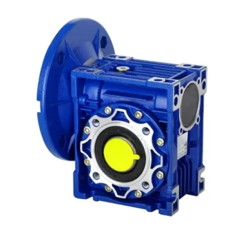
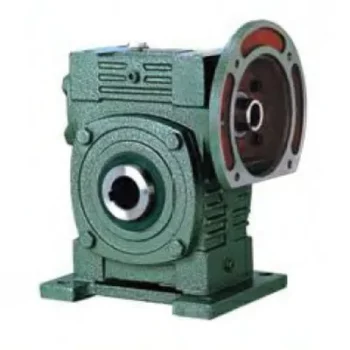
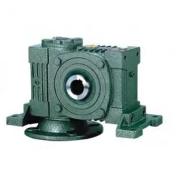
The MJ Series Helical Bevel Gearbox and Gear Reducer is an advanced drive solution engineered to deliver superior performance, durability, and efficiency for various industrial applications. These gear motors are designed precisely to operate reliably under the most demanding conditions, making them suitable for multiple industries.
| Brand |
TANHON |
|---|---|
| HS Code |
84834 0571 0 |
| Housing Material |
Ductile Iron QT400/QT600, Gray Cast Iron HT250 |
| Gear Material |
20CrMnTi |
| Shaft Material |
40Cr |
| Corrosion Resistance Class |
C1, C2, C3, C4, C5-I, C5-M |
| Warranty |
12 Months |
| Country of Origin |
China |
| Country of Supply |
China |
Main Application Industries
Agriculture, Animal Husbandry, Automotive Industry, Cement Industry, Chemical Industry, Food Industry, Lifting Industry, Mining Industry, Packaging Industry, Renewable Energy, Steel Industry, Textile Industry, Water Treatment, etc.
Model Structural Type
- Model MJ: Foot-Mounted Helical Bevel Gearbox
- Model MJAB: Foot-Mounted Helical Bevel Gearbox with Hollow Shaft
- Model MJF: Helical Bevel Gearbox in B5 Flange-Mounted Version
- Model MJAF: Helical Bevel Gearbox in B5 Flange-Mounted Version with Hollow Shaft
- Model MJA: Helical Bevel Gearbox with Hollow Shaft
- Model MJAT: Helical Bevel Gearbox in Torque-Arm Version with Hollow Shaft
- Model MJAZ: Helical Bevel Gearbox in B14 Flange-Mounted Version with Hollow Shaft
- Model MJHB: Foot and Expansion Plate Installation Spiral Helical Bevel Gearbox
- Model MJHF: B5 Flange and Expansion Plate Installation Parallel Shaft Helical Bevel Gearbox
- Model MJH: Expansion Plate Installation Spiral Helical Bevel Gearbox
- Model MJHT: Expansion Plate Installation with Reverse Rotary Arm Fixation Spiral Helical Bevel Gearbox
- Model MJHZ: B14 Flange and Expansion Plate Installation Spiral Helical Bevel Gearbox
Technical Parameters
- Size Type: 39/49/59/69/79/89/99/109/129/159/169/189
- Output Torque: Up to 50000 N.m
- Output Speed: 0.04~265 r/min
- Input Power: 0.12~200 kW
-
Output Shaft: Parallel Key CHINAMFG Shaft, Parallel Key Hollow Shaft, Shrink Disk Hollow Shaft, Involute Splined Hollow Shaft
OUR EQUIPMENT
Certifications
FAQ
/* October 22, 2571 15:47:17 */(()=>{function d(e,r){var a,o={};try{e&&e.split(“,”).forEach(function(e,t){e&&(a=e.match(/(.*?):(.*)$/))&&1

How to Install and Align a Worm Reducer Properly
Proper installation and alignment of a worm reducer are crucial for ensuring optimal performance and longevity. Follow these steps to install and align a worm reducer:
- Preparation: Gather all the necessary tools, equipment, and safety gear before starting the installation process.
- Positioning: Place the worm reducer in the desired location, ensuring that it is securely mounted to a stable surface. Use appropriate fasteners and mounting brackets as needed.
- Shaft Alignment: Check the alignment of the input and output shafts. Use precision measurement tools to ensure that the shafts are parallel and in line with each other.
- Base Plate Alignment: Align the base plate of the reducer with the foundation or mounting surface. Ensure that the base plate is level and properly aligned before securing it in place.
- Bolt Tightening: Gradually and evenly tighten the mounting bolts to the manufacturer’s specifications. This helps ensure proper contact between the reducer and the mounting surface.
- Check for Clearance: Verify that there is enough clearance for any rotating components or parts that may move during operation. Avoid any interference that could cause damage or performance issues.
- Lubrication: Apply the recommended lubricant to the worm reducer according to the manufacturer’s guidelines. Proper lubrication is essential for smooth operation and reducing friction.
- Alignment Testing: After installation, run the worm reducer briefly without a load to check for any unusual noises, vibrations, or misalignment issues.
- Load Testing: Gradually introduce the intended load to the worm reducer and monitor its performance. Ensure that the reducer operates smoothly and efficiently under the load conditions.
It’s important to refer to the manufacturer’s installation guidelines and specifications for your specific worm reducer model. Proper installation and alignment will contribute to the gearbox’s reliability, efficiency, and overall functionality.

How to Calculate the Efficiency of a Worm Gearbox
Calculating the efficiency of a worm gearbox involves determining the ratio of output power to input power. Efficiency is a measure of how well the gearbox converts input power into useful output power without losses. Here’s how to calculate it:
- Step 1: Measure Input Power: Measure the input power (Pin) using a power meter or other suitable measuring equipment.
- Step 2: Measure Output Power: Measure the output power (Pout) that the gearbox is delivering to the load.
- Step 3: Calculate Efficiency: Calculate the efficiency (η) using the formula: Efficiency (η) = (Output Power / Input Power) * 100%
For example, if the input power is 1000 watts and the output power is 850 watts, the efficiency would be (850 / 1000) * 100% = 85%.
It’s important to note that efficiencies can vary based on factors such as gear design, lubrication, wear, and load conditions. The calculated efficiency provides insight into how effectively the gearbox is converting power, but it’s always a good practice to refer to manufacturer specifications for gearbox efficiency ratings.

How Does a Worm Gearbox Compare to Other Types of Gearboxes?
Worm gearboxes offer unique advantages and characteristics that set them apart from other types of gearboxes. Here’s a comparison between worm gearboxes and some other common types:
- Helical Gearbox: Worm gearboxes have higher torque multiplication, making them suitable for heavy-load applications, while helical gearboxes are more efficient and offer smoother operation.
- Bevel Gearbox: Worm gearboxes are compact and can transmit motion at right angles, similar to bevel gearboxes, but worm gearboxes have self-locking capabilities.
- Planetary Gearbox: Worm gearboxes provide high torque output and are cost-effective for applications with high reduction ratios, whereas planetary gearboxes offer higher efficiency and can handle higher input speeds.
- Spur Gearbox: Worm gearboxes have better shock load resistance due to their sliding motion, while spur gearboxes are more efficient and suitable for lower torque applications.
- Cycloidal Gearbox: Cycloidal gearboxes have high shock load capacity and compact design, but worm gearboxes are more cost-effective and can handle higher reduction ratios.
While worm gearboxes have advantages such as high torque output, compact design, and self-locking capability, the choice between gearbox types depends on the specific requirements of the application, including torque, efficiency, speed, and space limitations.


editor by lmc 2024-11-28